Design and Implementation of Robotic Controlled Beans Planter using Mobile APP
-
Felix Oluwaseun Ayanniran

Computer Science Technology, Federal College of Agriculture, Ishiagu, Ebonyi, Nigeria
Raphael Segun Bello
Department of Agricultural Engineering, Federal College of Agriculture, Ishiagu, Ebonyi, Nigeria
Adisa Kehinde OlayinkaDepartment of Mechatronics, Lagos State University of Science and Technology, Nigeria
Joshua Ademolakun Ade-OmowayeDepartment of Mechanical Engineering (Mechatronics), Landmark University, Omu-Aran, Kwara, Nigeria
| Received 17 Nov, 2023 |
Accepted 03 Jun, 2024 |
Published 04 Jun, 2024 |
Background and Objective: This paper presents an innovative solution to enhance the efficiency and accuracy of planting beans in agricultural fields. Traditional manual planting methods are time-consuming and labor-intensive, often leading to inconsistent plant spacing and suboptimal yield. This paper aims to address these challenges by developing a robotic system that automates the planting process and allows remote control through a mobile application. Materials and Methods: The proposed robotic beans planter consists of a wheeled base equipped with planting modules, a seed house and a control unit. The planting modules are designed to create furrows in the soil at predetermined intervals and accurately dispense bean seeds. The seed house stores the seeds and provides a steady supply to the planting modules. The control unit comprises a microcontroller responsible for processing commands from the mobile app and coordinating the movements of the robot and seed dispensing mechanism. Results: The mobile application is developed to provide a user-friendly interface for farmers to control the Robotic Planter. Using the app, users can manipulate the robot to dig, plant and move the Planter. Additionally, real-time feedback from IR sensors and seed level sensors is relayed to the app to ensure precise operation and monitoring. The robotic planter project offers several advantages over traditional methods. It eliminates the need for manual labor, reducing the physical strain on farmers and potentially increasing planting speed. The machine ensures uniform spacing between plants and consistent planting depth, resulting in improved crop yield and reduced resource wastage. Conclusion: The integration with a mobile app enables remote operation and monitoring, allowing farmers to control the robot from a distance and make real-time adjustments as needed.
| Copyright © 2024 Ayanniran et al. This is an open-access article distributed under the Creative Commons Attribution License, which permits unrestricted use, distribution, and reproduction in any medium, provided the original work is properly cited. |
INTRODUCTION
The conventional manual method has traditionally been used for seeding, but numerous issues plagued it that need to be addressed1. The conventional approach relies on human labor and outdated techniques, which are time-consuming and require significant effort. Humans need breaks and cannot work in hazardous environments. Additionally, when large wheels are used on muddy soil, they may compact the soil. Skilled manpower is essential in agriculture, but this requirement can be met by automating the process of soil loosening and seed sowing using robots. Therefore, the conventional system has several problems that need to be addressed1.
In this present era of globalization, several researchers are striving to enhance the efficiency and speed of automation-related work within a short timeframe. As there is a growing demand for higher quality agricultural products and a shortage of available labor in rural areas, conducting innovative research in the agricultural field has become a crucial task2. Scientists are not only focused on advancing automation but also on creating robot navigation systems. Robots have become increasingly important in the agricultural industry for various farming processes. Robotics is a field that involves utilizing an electromechanical system, known as a robot, to fulfill assigned tasks by following specific instructions2.
Currently, the need for agricultural machinery that minimizes human labor and time is growing. Additionally, advancements in the Internet of Things (IoT) and robotics have led to the development of smarter farming equipment developed a prototype of an autonomous agriculture robot that is designed for seed sowing tasks3. They found that this AGRIBOT(Agriculture robot) can sow seeds at the appropriate depth and distance between crops and rows for optimal results4. Numerous studies have attempted to address comparable challenges in the field of agriculture by suggesting task-specific robots such as self-driving tractors5. Aging farmers pose a significant issue in agriculture. One of the contributing factors to the younger generation's disinterest in the field is the absence of technological advancements that make it seem unchallenging. The specific objectives of the project are to design and develop a seed planter with sensors and actuators that can plant seeds at a consistent depth and spacing. The planter should be able to operate autonomously.
MATERIALS AND METHODS
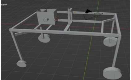
Design and system overview: The study was carried out at the Federal University, Oye-Ekiti, Ekiti State. The study started in December, 2022 and ended in June, 2023. The AutoCAD of the machine configuration is shown in Fig. 1. The design consists of a microcontroller (The brain of the robot), sensors, DC motors, power supply unit, a metal frame, wheels and a seed container. The wheels enable the robot to achieve locomotion within its space. The sensors enable it to monitor certain variables in real time such as the seed level at any given time and send the status to the controlling mobile app (Ultrasonic Sensor) and help protect the robot, humans, or any other object within the environment of the robot while in operation (IR Sensor). The seed catcher contains a mechanism that helps catch 3-4 bean seeds and drop them into the hole via a funnel-like channel.
|
|
A crank-slider mechanism that helps achieve digging on the ridges; while an Arduino Uno Microcontroller coordinates the entire operation.
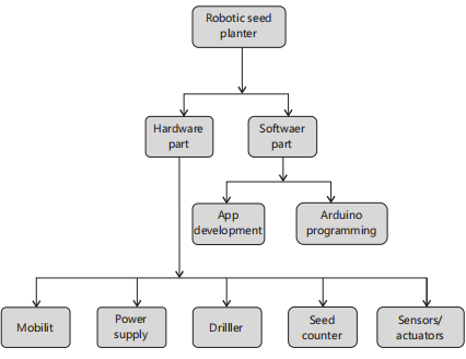
Block diagram of the system: The block diagram of the entire design is shown in (Fig. 2).
Hardware part: The hardware part consists of all the physical components of the robot and how they are linked together to work with one another. It comprises of the mobility, power supply, drill/dig section, seed catching and planting section and the sensors and actuators used.
Software part: This part is all about the aspect of the project execution that deals more with the controls and logic of the robot and it all has to do with writing computer programs.
Mobility: This section has to do with the mechanisms involved in the navigation and locomotion of the robot in its workspace (farmland). The mobility section has a frame on which the entire system is hosted. It incorporates a wheeled system of locomotion because this system when compared with a legged or skid mechanism, enables the robot to move faster with less energy and complexity of design. It also has good stability and simplicity of mechanism. To ensure proper balance in uneven terrain, a four wheels front drive system was employed instead of three wheels or a combination of two wheels plus standard balanced castor wheels. The choice of standard wheels used are those with high threads (off-road) to avoid wheel slip (or ensure firm grip) while moving on any terrain. These four wheels are controlled with signals from the microcontroller via DC. The movement directions are achieved thus:
- Forward motion: Front wheels rotate in a clockwise direction with the same speed signal
- Reverse direction: Front wheels rotate in a counter-clockwise direction with the same speed signal
The mobility section has a frame on which the entire system is hosted.
Power supply: This section comprises a 12v battery, which serves as the main power supply unit for the robot operations. The wiring packaging of the Arduino Microcontroller and other electronic components are also handled in this section. The 12v system is a lead acid battery.
Driller/digger: This section deals with the mechanism for drilling the soil for planting seeds. It utilizes a crank-slider mechanism that carries the pointed-nose digger up and down to make the seed hole. The digger length is a calculated length.
Seed counter: This section is where the seed catching and dropping is done. It comprises of a container and a sensor to achieve monitoring operations and report the status to the farmer via the mobile app. It has a catcher disc with notches along the circumference to catch 2-4 seeds. Attached to this container is a DC motor that rotates the seed catcher. A funnel-like channel is connected to the other end of the catcher disc. From here, the seed is channeled into the soil after the drilling is done. The container has two compartments.
One at the top of the seed compartment is an ultrasonic sensor to help monitor the level of the beans in the container and send the result to the controlling mobile app in real-time.
Sensors and actuators: This section is made up of the various sensors and actuators used in the project. An IR sensor is used to prevent obstacle collision during the fully autonomous mode of the system.
If an obstacle is detected, the robot stops momentarily and the farmer is notified via the app and necessary actions are taken. It also includes an ultrasonic sensor that monitors the level of seed in the container. Actuators in the project include DC motors.
Mobile application development: To enable the farmer to control the robot remotely, a mobile app was specifically built for the robot. This app was specially made for this robot using Flutter framework. The app code was written with Dart programming language. The app makes a connection with the Arduino via Bluetooth connection.
Arduino programming: Arduino is an open-source electronics platform based on easy-to-use hardware and software. Here the code that controls the robot is written and Arduino IDE on a windows 10 OS Computer and compiled onto the Arduino microcontroller. This code allows the robot to communicate with the sensors and actuators as well as the Bluetooth module and the mobile app. Commands are received from the app and via a switch-case function, the command is decoded and carried out as required.
Motor driver is used with the Arduino to control the DC motors because drawing large current from the board can damage it. With the aid of a driver, a signal is received from the microcontroller and the DC motors are activated accordingly. The motors draw current from the 12v battery via the driver, ensuring the microcontroller is safe.
Component used
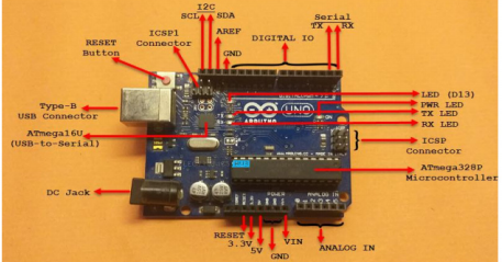
Arduino micro controller: This is the heart of the systems controlling and coordinating the operations of the system. Arduino Uno microcontroller (Fig. 3) is used in preference to Nano because Uno has more connectors and pins than Nano. Arduino Uno is a widely used open-source microcontroller board that has played a pivotal role in making electronics and programming accessible to a wide range of students and professionals. Developed by the Italian company Arduino, the Arduino Uno is renowned for its simplicity, versatility and ease of use. An ATmega328P microcontroller, which is part of the AVR family powers it.
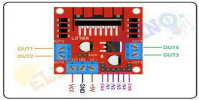
L298N h-bridge driver module: To have a total control over the DC motor, it is important to control its speed and direction. This can be achieved by combining these two techniques: PWM- for speed control and H-Bridge- for direction control (Fig. 4). This module combines the aforementioned techniques. It is able to control two DC motors and can handle current up to 1.5A.
|
|
| Table 1: | Motor direction pin configuration | |||
| Sample code | Classification |
| AB1 (100/0%) | Control (100 g wheat flour) |
| AB2 (90/10%) | 90% wheat flour+10% watermelon rind flour |
| AB3 (80/20%) | 80% wheat flour+20% watermelon rind flour |
| AB4 (70/30%) | 70% wheat flour+30% watermelon rind flour |
| AB5 (60/40%) | 50% wheat flour+50% watermelon rind flour |
The module has two direction pins for each channel as shown in Table 1. The IN1 and IN2 pins control the direction of the first motor while IN3 and IN4 pins control the direction of the second motor. The motor direction can be controlled by applying either a logic HIGH (5v) or logic LOW (0v) to the direction pins.
The ENA and ENB on the modules are used to turn the motors ON respectively. They are active high pins. Speed control is achieved with PWM. Removing some particular jumpers on the board makes the board ready to have the motor speed set programmatically by connecting them to PWM enabled pins on Arduino such as pins 3, 5, 6, 9, 10 and 11.
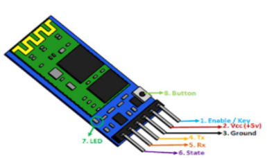
HC-05 bluetooth module: The HC-05 (Fig. 5) is a widely used Bluetooth module that enables wireless communication between electronic devices. It provides a convenient and low-cost solution for adding Bluetooth connectivity to various projects, ranging from robotics and IoT devices to home automation and wearable gadgets. The HC-05 module is based on Bluetooth version 2.0+EDR (Enhanced Data Rate), which provides faster data transmission and improved connectivity compared to earlier versions. It offers a typical communication range of about 10 m, but this can vary based on environmental conditions and obstacles. It typically operates at 3.3V, but some variants might support 5V logic levels, depending on the module's design.
|
|
The HC-05 module usually has six pins, including:
- VCC: Connects to the supply voltage (3.3V or 5V)
- GND: Ground connection
- TXD: Transmit data pin (for sending data from the module)
- RXD: Receive data pin (for receiving data to the module)
- STATE: Indicates the current state of the module (pairing, connected, etc.)
- EN (or KEY): Enables/disables the module's AT command mode
To use the HC-05 module:
- Connect VCC to the supply voltage (3.3V or 5V) and GND to ground
- Connect TXD on the module to the RX pin on your microcontroller and RXD to the TX pin
- One might need to connect the EN (or KEY) pin to a microcontroller pin to control the module's mode
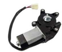
Vehicle power window motor: Vehicle power window motor (Fig. 6) is a high torque Direct Current motor used for the navigation system. The high value of the torque is needed to overcome the inertia of the system in order to move from rest and continue moving until a stop command or signal is sent. The following are the technical specifications:
|
Specifications:
- Voltage rating: 12VDC
- Rated speed: 60 RPM
- Rated torque: 2.9 N.m (30 kgf.cm)
- Stall torque (locked): 9.8N.m (100 kg.cm)
Off-road wheels: The wheels (Fig. 7) for the robot were specially and locally fabricated using PVC pipes, bolts and nuts, Bicycle tires, shoe ethylene vinyl acetate (EVA) and adhesives. It has a very high threading to maintain grip in the farmland terrain and prevent slipping conditions. The wide width makes it have a larger contact patch with the road, which can improve traction during acceleration and cornering.
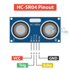
Ultasonic sensor: Ultrasonic sensors (Fig. 8) are devices that use sound waves with frequencies above the audible range of human hearing (typically above 20 kHz) to detect objects, measure distances and determine the presence of obstacles. They work based on the principle of echolocation, similar to how bats and dolphins navigate in their environments. An ultrasonic sensor typically consists of the following components:
- Transmitter: Emits ultrasonic sound waves
- Receiver: Detects the reflected sound waves
- Control circuit: Generates the ultrasonic pulses and measures the time delay
- Housing: Protects the internal components and focuses the emitted sound waves
The application areas include distance Measurement, Obstacle Sensing, Level Sensing, Proximity Sensing, Flow Measurement and Object Counting. It is used in this project to detect beans levels in a container.
Connecting it to Arduino involves the following steps:
Connect VCC and GND:
- Connect the VCC pin of the ultrasonic sensor to the 5V pin on the Arduino
- Connect the GND pin of the ultrasonic sensor to the GND pin on the Arduino
Connect trigger and echo pins:
- Connect the trigger (TRIG) pin of the ultrasonic sensor to a digital pin on the Arduino (e.g., Pin 7)
- Connect the echo (ECHO) pin of the ultrasonic sensor to another digital pin on the Arduino (e.g., Pin 8)
|
|
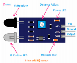
IR sensors: Infrared (IR) sensors (Fig. 9) are devices that detect and respond to electromagnetic radiation in the infrared wavelength range. These sensors are commonly used to detect the presence of objects, measure distances and monitor temperature changes. They work based on the principle that objects emit or reflect infrared radiation, which is not visible to the human eye but can be detected by specialized sensors.
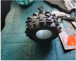
Seed catcher: The seed catcher is an assembly of several components including, a geared DC motor for rotating the catcher. It is mounted just outside the container. Inside the container is a catcher made up of two circular discs and a shoe EVA (ethylene vinyl acetate) all fastened together. The EVA is notched at two points to capture beans and drop them in the appropriate place every 360 degree rotation of the disc. The seed compartment is specially crafted to ensure optimal consumption of the seed. This crafting involves beveling the base of the compartment to ensure that all beans in the compartment always drift towards the disc. The beveled structure is made on a Polystyrene foam. This material was preferred because of its very lightweight and the ease with which can be shaped. Material used in the entire fabrication should be light weighted as much as possible so as not to increase the normal reaction due to the average weight of the system, consequently increasing the torque required to provide appropriate traction to move the robot. The higher the torque requirement the greater the cost. But engineering aims to balance cost with performance. This fact was put into consideration while selecting materials for the project.
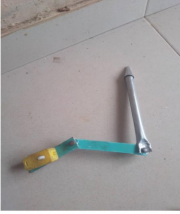
Driller or digger: The driller (Fig. 10) was built on the slider-crank mechanism. The rotational motion of a geared DC motor was translated into linear motion of the digger shaft constrained in a guide attached to the frame of the robot. The shaft is made to have a pointed nose in order to have high pressure (Force per unit area) on the soil hence reducing the torque requirement to dig a hole on a wet or moderate heap. The digging is completed in a 360-degree rotation of the DC motor. The seed is dropped after the digging is completed.
|
|
Power supply unit: The major power supply unit for this project is a lead-acid accumulator battery. Lead-acid accumulator batteries, commonly known as lead-acid batteries, are a type of rechargeable battery that has been used for decades in various applications due to their reliability and cost-effectiveness. It has a voltage of 12 volts and a capacity of 4.5Ah.
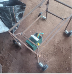
Body design: The frame structure (Fig. 11) of the Robotic Beans Planter was fabricated with a steel pipe of 15 by 15 mm (light weight) type. The fastening type employed was welding since the intention is to make it permanent. Some other parts were fastened together with bolts and nuts, like the adjustment of the system’s base with respect to the frame to be able to adjust the height of the robot according to the height of the ridges it is working on. The chassis is also painted to prevent it from corrosion.
Softwares used
Blender: Blender 2.79b is a software used to create 3D models of products, prototypes and mechanical components. Engineers can accurately model intricate parts, assemblies and mechanisms. The software's
rendering capabilities enable realistic visualizations that can assist in design reviews and presentations. All the 3D models used in this project were done using Blender.
Fritzing: Fritzing is an open-source software tool designed to facilitate the creation of electronic circuits, schematics and printed circuit boards (PCBs) for both beginners and advanced users. It aims to simplify the process of turning your electronic projects and ideas into reality by providing an intuitive interface and a set of powerful tools. All circuits in this project were designed using Fritzing.
Android studio: Android Studio is the official integrated development environment (IDE) provided by Google for developing Android applications. It's a powerful and feature-rich tool that streamlines the entire process of designing, coding, testing and deploying Android apps. The mobile app for this project was built using this IDE or code editor using Flutter framework and Dart programming language.
The Arduino Integrated Development Environment (IDE) is a software platform specifically designed for programming and developing projects using Arduino boards. The Arduino IDE provides a user-friendly environment for writing, compiling and uploading code to Arduino microcontrollers. It offers a simple code editor with features like syntax highlighting, automatic indentation and code completion to assist in writing clean and error-free code. It supports both C and C++ languages. It was installed on a Windows 10 computer.
Design calculations
Digger calculations:
- Length of motor arm (crank): 9 cm
Digger range (stroke) : S = 2×√{L2-r2×sin2 (θ2)} |
(1) |
- L = Length of connecting rod
- r = Length of crank
- θ = Angle through which the crank has rotated 32
- L = 10.5 cm
- r = 9 cm
- Smax occurs when = 180
- Substituting these values: S = 10.81 cm
- Digger will move up and down by 10.81 cm
Though planting depth depends on factors such as soil type, seed size, climate etc., the average depth for common beans variety is 2.5-3.8 cm.
Traction and motor torque calculation:
- Weight of system = 5.44 kg
- Coefficient of friction, μ between tires and farmland = 0.7 (average value between 0.6 and 0.8 was used)
- Wheel diameter = 11 cm = 0.11 m (r = 0.055 m)
- Fr = μN 1
Fr = 0.7×5.44×9.81 = 37.35N |
(2) |
- Minimum traction that must be provided by the robot wheels in contact with the ground is 37.35N (Neglecting other factors affecting inertia)
Torque requirement = Fr×r |
(3) |
- T1 = 37.35×0.055 = 2.05N-m
- Minimum torque requirement = 2.05N-m
- At least 2 m/s2 acceleration is required, Therefore
- F = 5.44×2 = 10.88N (F = MA)
- T2 = 10.88×0.055 = 0.5984 Nm
- Total torque requirement = T1+T2
- T = 2.05+0.5984 = 2.6484N-m (Selected motor torque has 2.9Nm rated torque)
RESULTS
The objective of this paper is to design a robotic bean planter that can plant beans and controlled via a mobile app. The main operations include navigation, digging and planting.
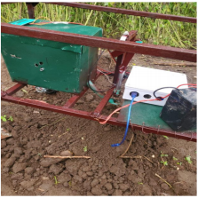
Testing of digging section: The planter robot (Fig. 12) includes a digging section. The digging incorporates a slider-crank mechanism. The machine was tested and a digging operation was performed successfully.
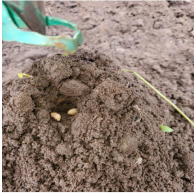
Testing of planting section: After the digging was concluded, it is proceeded to testing the planting in (Fig. 13). It was observed that the planter module dropped seeds within the range of 2-4. This is still acceptable for bean planting.
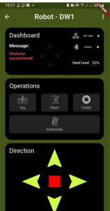
Testing and evaluation of robot sensors: From (Fig. 14) The Ultrasonic sensor monitoring the seed level in the container and the IR sensor checking for obstacles were both tested. The seed level sensor reported in real time the level of the beans in the container and sent the level to the user via the mobile app. The proximity sensor monitors the frontal area of the robot and sends the message “Obstacle encountered” to the user via the app.
DISCUSSION
The robotic beans planter leverages a seed catcher mechanism and a crank-slider hole digging mechanism to automate the seed planting process. The results offer several significant implications and discussions.
Precision agriculture enhancement: The precise seed dropping and uniform hole digging showcased by the robotic planter contributes to precision agriculture. Farmers can expect improved yield and resource utilization, reducing costs and environmental impact.
Labor and time savings: The robotic planter's ability to operate autonomously reduces the need for manual labor during the planting phase. This results in time savings and potentially reduces labor expenses for farmers.
|
|
|
Consistent germination: Uniform seed placement at the correct depth promotes consistent germination and even crop growth. The robotic planter's accurate seed dropping mechanism ensures each seed receives the optimal conditions for sprouting.
Scalability and adaptability: The project's outcomes extend to scalability and adaptability. The robotic planter concept can be applied to larger agricultural fields, enhancing its potential impact on agricultural practices.
Educational and outreach potential: The project's innovative approach to combining robotics and agriculture hold educational value. It can inspire students and enthusiasts to explore interdisciplinary applications of technology in solving real-world challenges.
Challenges and future work: The discussion includes considerations of challenges faced during design and fabrication, such as mechanical design complexities, power supply management and control system implementation. Future work may involve refining the design for efficiency, incorporating advanced sensing for soil conditions and addressing potential issues identified during testing.
The conventional manual method has traditionally been used for seeding, but numerous issues plagued it that need to be addressed1. The conventional approach relies on human labor and outdated techniques, which are time-consuming and require significant effort. Humans need breaks and cannot work in hazardous environments. Additionally, when large wheels are used on muddy soil, they may compact the soil. Skilled manpower is essential in agriculture, but this requirement can be met by automating the process of soil loosening and seed sowing using robots. Therefore, the conventional system has several problems that need to be addressed 1.
In this present era of globalization, several researchers are striving to enhance the efficiency and speed of automation-related work within a short timeframe. As there is a growing demand for higher quality agricultural products and a shortage of available labor in rural areas, conducting innovative research in the agricultural field has become a crucial task2.
Scientists are not only focused on advancing automation but also on creating robot navigation systems. Robots have become increasingly important in the agricultural industry for various farming processes. Robotics is a field that involves utilizing an electromechanical system, known as a robot, to fulfill assigned tasks by following specific instructions2.
Currently, the need for agricultural machinery that minimizes human labor and time is growing. Additionally, advancements in the Internet of Things (IoT) and robotics have led to the development of smarter farming equipment3 developed a prototype of an autonomous agriculture robot that is designed for seed sowing tasks. They found that this AGRIBOT can sow seeds at the appropriate depth and distance between crops and rows for optimal results4.
Numerous studies have attempted to address comparable challenges in the field of agriculture by suggesting task-specific robots such as self-driving tractors5. Aging farmers pose a significant issue in agriculture. One of the contributing factors to the younger generation's disinterest in the field is the absence of technological advancements that make it seem unchallenging.
CONCLUSION
In this project, a robotic seed planter controlled via mobile app was designed and implemented successfully. About 85% of the components were locally fabricated with local materials and tests were done on the field to ensure that it works satisfactorily. However certain improvements can be done to make it perform better. Refining the design for efficiency, incorporating advanced sensing for soil conditions and addressing potential issues identified during testing may be involved in future.
SIGNIFICANCE STATEMENT
Traditional manual planting methods are time-consuming and labor-intensive, often leading to inconsistent plant spacing and suboptimal yield. This paper aims to address these challenges by developing a robotic system that automates the planting process and allows remote control through a mobile application. This paper provides a more efficient and less labor-intensive way of planting seeds that will improve crop yield and reduce waste. By automating the planting process and providing real-time data, this system will enable farmers to optimize their planting process, resulting in higher crop yields and more efficient use of resources. Future work may involve refining the design for efficiency, incorporating advanced sensing for soil conditions and addressing potential issues identified during testing.
REFERENCES
- Yedave, V., P. Bhosale, J. Shinde and J. Hallur, 2019. Automatic seed sowing robot. Int. Res. J. Eng. Technol., 6: 2005-2007.
- Chame, N., M. Jadhav, P. Tele and S.P. Hon, 2018. Design and implementation of automatic seed sowing robot. Int. J. Res. Eng. Sci. Manage., 1: 102-103.
- Kumar, P. and G. Ashok, 2021. Design and fabrication of smart seed sowing robot. Mater. Today Proc., 39: 354-358.
- Khosravi, J., M.A. Asoodar, M.R. Alizadeh and M.H. Peyman, 2011. Application of multiple criteria decision making system compensatory (TOPSIS) in selecting of rice milling system using. World Appl. Sci. J., 13: 2306-2311.
- Noguchi, N. and O.C. Barawid, 2011. Robot farming system using multiple robot tractors in Japan agriculture. IFAC Proc. Volumes, 44: 633-637.
How to Cite this paper?
APA-7 Style
Ayanniran,
F.O., Bello,
R.S., Olayinka,
A.K., Ade-Omowaye,
J.A. (2024). Design and Implementation of Robotic Controlled Beans Planter using Mobile APP. Trends in Applied Sciences Research, 19(1), 112-125. https://doi.org/10.3923/tasr.2024.112.125
ACS Style
Ayanniran,
F.O.; Bello,
R.S.; Olayinka,
A.K.; Ade-Omowaye,
J.A. Design and Implementation of Robotic Controlled Beans Planter using Mobile APP. Trends Appl. Sci. Res 2024, 19, 112-125. https://doi.org/10.3923/tasr.2024.112.125
AMA Style
Ayanniran
FO, Bello
RS, Olayinka
AK, Ade-Omowaye
JA. Design and Implementation of Robotic Controlled Beans Planter using Mobile APP. Trends in Applied Sciences Research. 2024; 19(1): 112-125. https://doi.org/10.3923/tasr.2024.112.125
Chicago/Turabian Style
Ayanniran, Felix, Oluwaseun, Raphael Segun Bello, Adisa Kehinde Olayinka, and Joshua Ademolakun Ade-Omowaye.
2024. "Design and Implementation of Robotic Controlled Beans Planter using Mobile APP" Trends in Applied Sciences Research 19, no. 1: 112-125. https://doi.org/10.3923/tasr.2024.112.125

This work is licensed under a Creative Commons Attribution 4.0 International License.